螺栓预紧力作用下的C型夹具蠕变计算
责任编辑:
1440分钟
时间:2024-01-17
来源:转载于:https://mp.weixin.qq.com/s/iRywq0O7Gvgu2-RyiTMSrw
责任编辑:
1440分钟
时间:2024-01-17
来源:转载于:https://mp.weixin.qq.com/s/iRywq0O7Gvgu2-RyiTMSrw
1.问题的描述
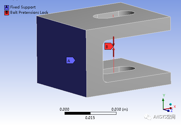
如图所示给出了螺栓预紧力作用下的C型夹具蠕变计算模型,该模型由C型夹具和线体螺栓组成。线体螺栓的材料为结构钢,C型夹具的弹性模量为2e11Pa,泊松比为0.3,蠕变模型使用时间强化模型(Time Hard),C1=2E-20,C2=1.1,C3=1.5,C4=0。如图所示,完全固定C型夹具的A位置面,在线体螺栓上施加8000N的螺栓预紧力,计算采用两个载荷步,预紧后激活蠕变,蠕变的计算时间为10000s。
图2 结构静力学分析系统图
单击结构静力学分析系统中的工程数据(Engineering Data)子模块,在Material选项中定义C型夹具材料名称为夹具,然后在左侧Toolbox,双击蠕变模块下方的Time Hardening,然后按照如图3所示,输入夹具材料参数。
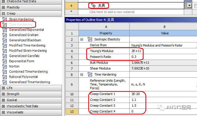
图3 夹具材料数据
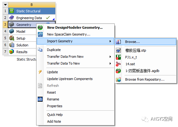
图4 导入模型
单击Model>Geometry>Solid,则弹出如图5所示的模型细节设置面板,用户按照图5所示的将材料分配为夹具。
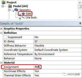
图5 模型细节设置面板
右击Connection>Insert>Joint,在弹出的如图6所示的运动副设置细节面板,设置连接类型(ConnectionType)为体-体连接(Body-Body),设置类型(Type)为固定(Fixed),参考位置(Reference)为线体螺栓的定点;运动位置(Mobile)为C型夹具内孔四个侧面,具体位置如图6所示,设置球形区域(PinballRegion)半径1.5e-2m。
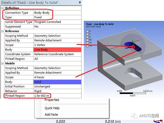
图6 运动副设置细节面板
右击Connection>Insert>Joint,在弹出的如图7所示的运动副设置细节面板,设置连接类型(ConnectionType)为体-体连接(Body-Body),设置类型(Type)为固定(Fixed),参考位置(Reference)为线体螺栓的定点;运动位置(Mobile)为C型夹具内孔四个侧面,具体位置如图7所示,设置球形区域(PinballRegion)半径1.5e-2m。
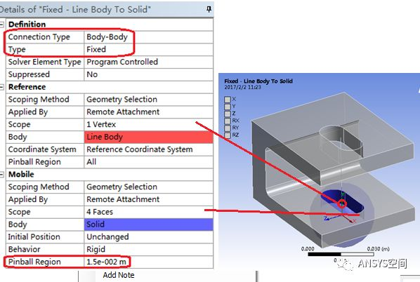
图7 运动副设置细节面板
右击Mesh>Method,弹出如图8所示的Mesh方法设置细节面板,选择作用的体为C型夹具,设置Method为MultiZone,右击Mesh,选择Generate Mesh,完成网格划分。
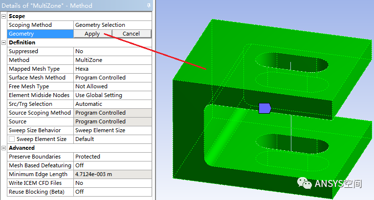
图8 Mesh方法设置细节面板
单击Analysis Settings,弹出如图9所示的静力学分析设置面板,设置载荷步数(Number of Steps)为2,第一个载荷步按照如图10所示进行设置;第二个载荷步按照如图5-11所示进行设置。
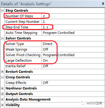
图9静力学第一个载荷步设置
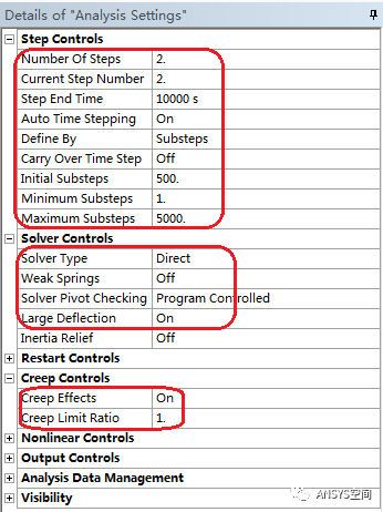
图10静力学第二个载荷步设置
右击StaticStructural,选择Insert> FixedSupport,在细节窗口弹出如图11所示的定义固定支撑设置面板,选择C型夹具的侧面,单击Apply,其他设置按照图5-12进行设置。
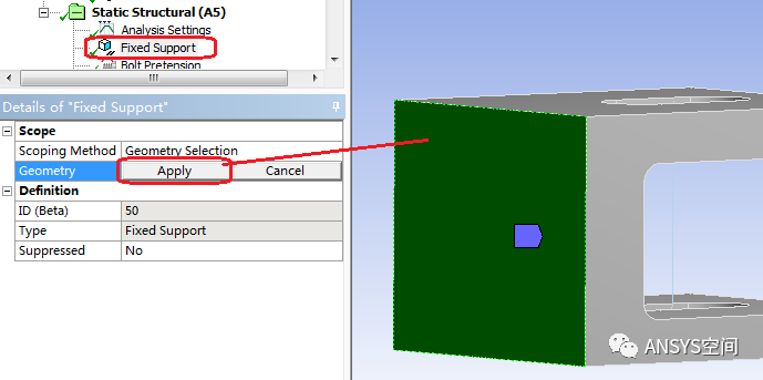
图11定义固定支撑设置面板
右击Static Structural,选择Insert>Bolt Pretension,弹出如图12所示螺栓预紧载荷的细节设置面板,定义作为位置为线体螺栓,同时在软件界面的右侧下方出现如图13所示的螺栓载荷定义面板,按照如图5-14进行设置。
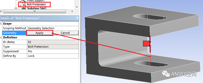
图12 螺栓预紧载荷的细节设置面板
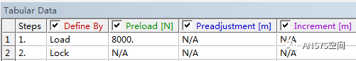
图13 螺栓载荷定义面板
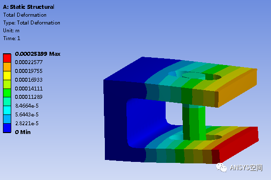
图14 1s时刻的总体变形云图
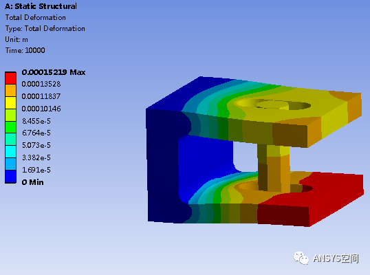
图15 10000s时刻的总体变形云图
/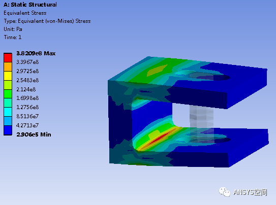
图16 1s时刻的等效应力云图
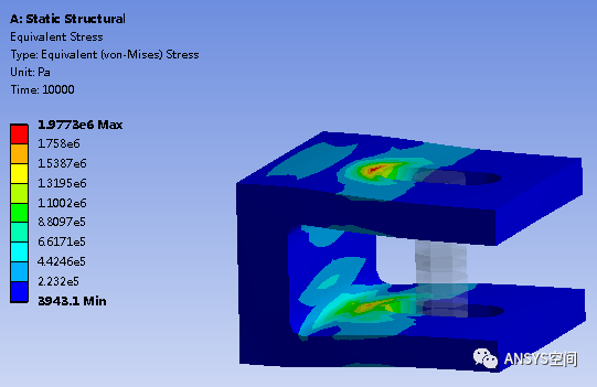
图17 10000s时刻的等效应力云图
来源:转载于:https://mp.weixin.qq.com/s/iRywq0O7Gvgu2-RyiTMSrw