ANSYS Workbench轮-轨接触有限元分析
责任编辑:
沙克
时间:2023-04-16
来源:转载于:ANSYS空间
责任编辑:
沙克
时间:2023-04-16
来源:转载于:ANSYS空间
1.问题描述
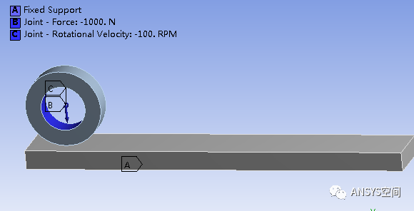
如图所示给出了轮-轨接触模型,该模型由圆形钢质轮和钢质平板组成,轮和轨道的材料都为结构钢。完全固定约束轨道底面,在钢质轮子的内孔施加运动副载荷,包括垂直压力1000N和旋转速度,旋转速度在0到1s之间由0RPM加速到100RPM,摩擦系数为0.1。
启动Workbench,双击Workbench工具箱中的用户系统Transient Structural,弹出如图所示的瞬态结构动力学分析系统。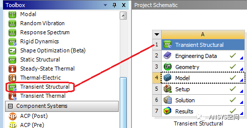
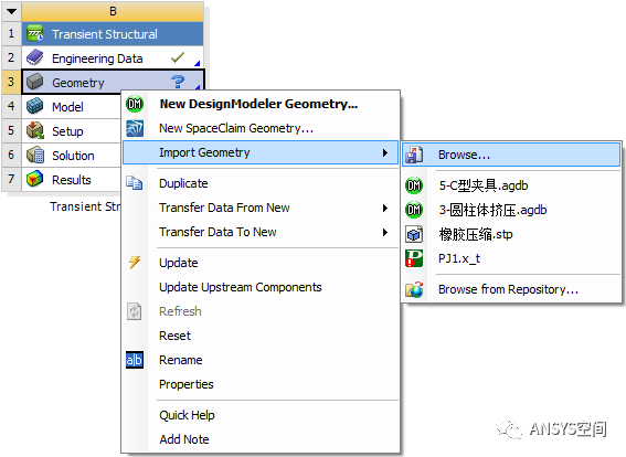
图 导入模型
单击Connection>Contacts>Frictional-SolidTo Solid,弹出如图所示接触细节设置面板,设置接触类型(Type)为Frictional,摩擦系数为0.1,具体设置如图所示。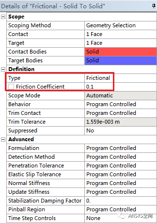
图 接触细节设置面板
右击Connection>Insert>Joint,在弹出的如图所示的运动副设置细节面板,设置连接类型(Connection Type)为体-地面连接(Body-Ground),设置类型(Type)为通用运动副(General),释放X和Y方向的平动自由度,释放绕Z方向的转动自由度,选择作用位置为轮子的内孔表面。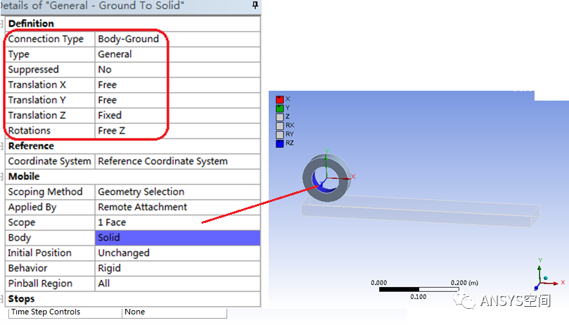
图 运动副设置细节面板
弹出如图所示的网格划分细节设置面板,设置Relevance Center为中级(Medium),其他保持默认设置,然后右击Mesh,选择Generate Mesh,生成的网格如图所示。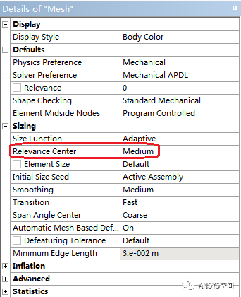
图 网格划分细节设置面板
单击Analysis Settings,弹出如图所示的结构瞬态动力学分析设置面板,将自动时间步(Auto Time Stepping)设置为On,定义方式(Define By)设置为Substeps,初始子步为(Initial Substeps)100,最小子步(Minimum Substeps)为50,最大子步为2000,将Large Deflection设置为On,表示打开了大变形分析。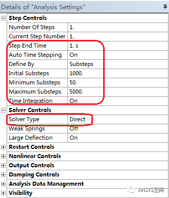
图 分析设置细节面板
右击Transient,选择Insert>Fixed,在细节窗口弹出如图所示的位移约束细节设置面板,选择轨道的底面,单击Apply。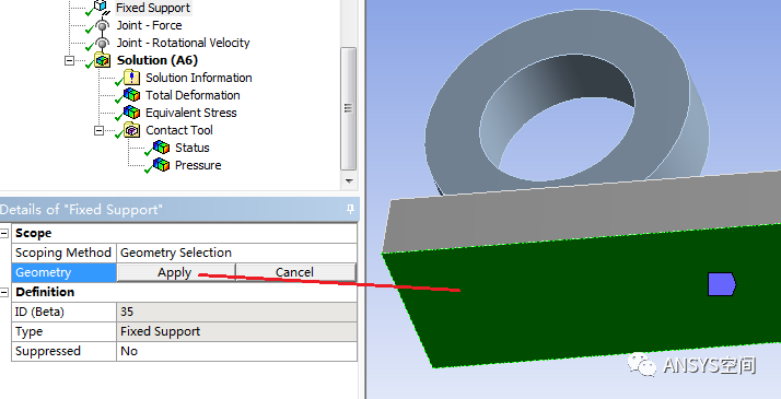
右击Transient,选择Insert>Joint Load,单击Joint Load,显示如图所示的运动副载荷设置面板,下列选择运动副为General-Ground To Solid,DOF为Y Displacement,Type为Force,然后在右侧弹出的表格中输入载荷为-1000N
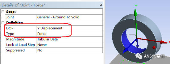
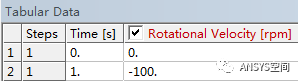
图 运动副载荷设置面板
右击Transient,选择Insert>Joint Load,单击Joint Load,显示如图所示的运动副载荷设置面板,下列选择运动副为General-Ground To Solid,DOF为RotationZ,Type为Rotational Velocity,然后在右侧弹出的表格中输入转速0-0;1-(-100),负号表示转动方向。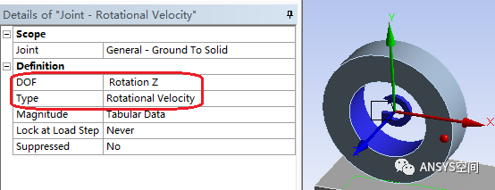

图 运动副载荷设置面板
选择Transient>Solution,右击Solution,选择Solve。
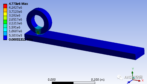
图 182e-3s时刻的等效应力云图
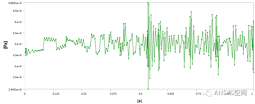
图 最大等效应力与时间的关系
来源:转载于:ANSYS空间