时间:2021-01-27 来源:转载于:仿真秀
第二部分:网格划分
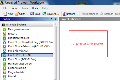
2.1 启动ANSYS Workbench,从Analysis Systems中拖拽一个FLUENT仿真流程到Project Schematic中。
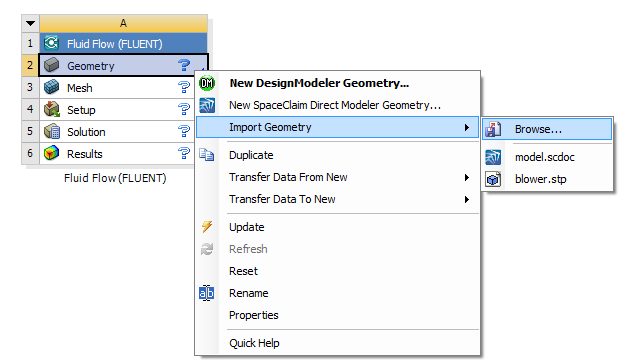
2.2 在FLUENT仿真流程中,鼠标右键点击Geometry,选择Import Geometry --> Browse,选择刚才保存的model.scdoc文件。
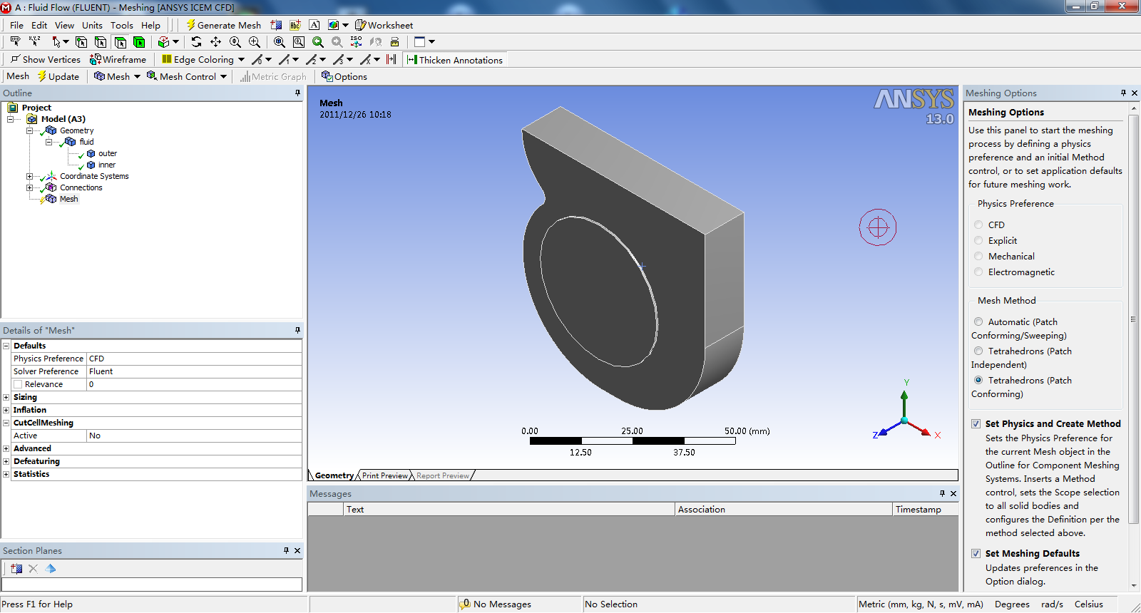
2.3 在FLUENT仿真流程中,鼠标右键点击Mesh,选择Edit,启动ANSYS Meshing工作界面。
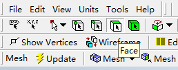
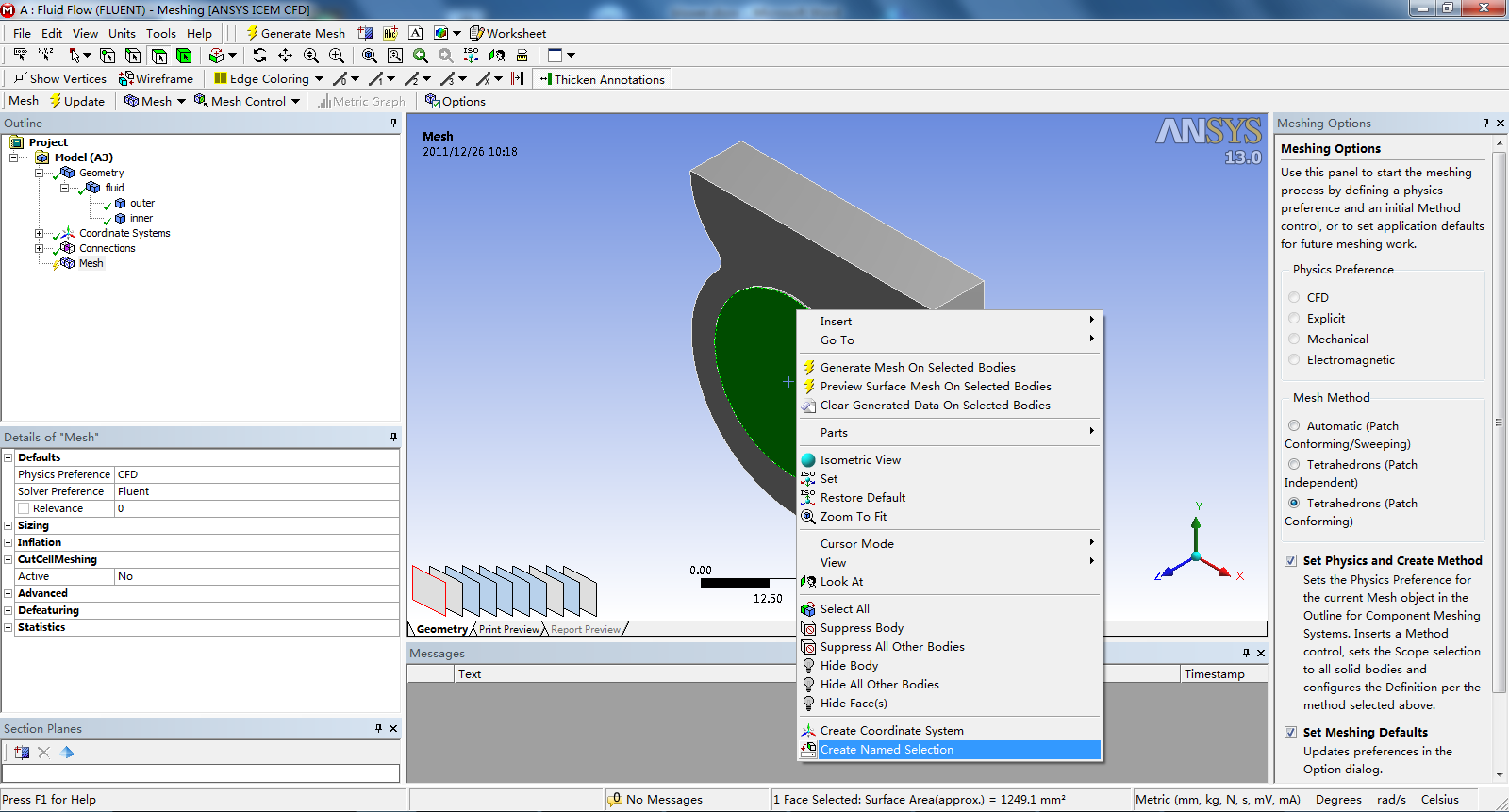
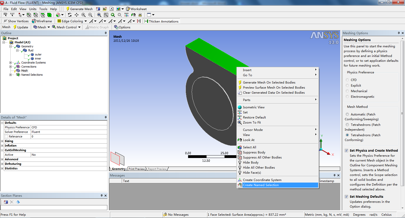
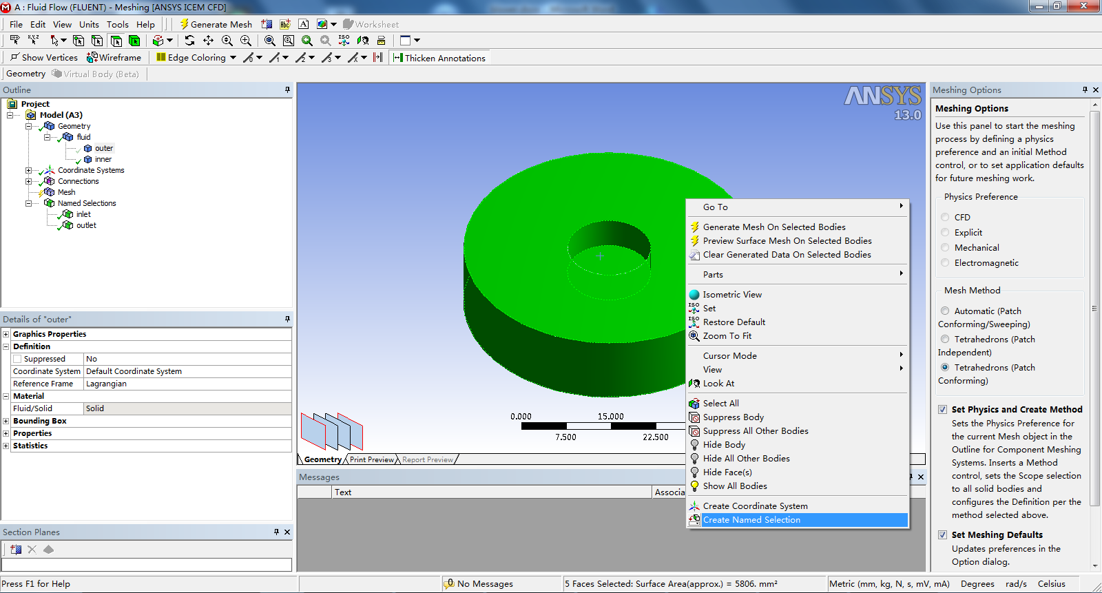
2.4 在工具栏中将选择的方式设定为选择Face,选中风机的入口圆形表面,点击鼠标右键,选择Create Named Selection,并在弹出的Selection Name窗口中输入新的名称inlet。
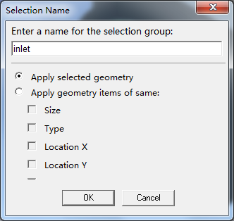
2.5 使用2.4同样的方法,定义风机的出口矩形表面新名称outlet。
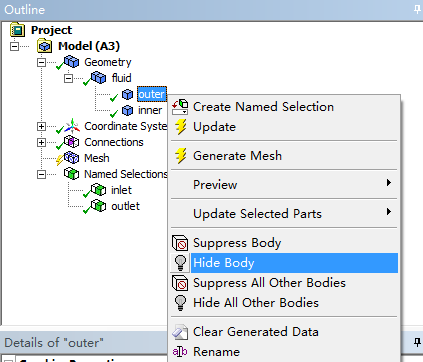
2.6 展开目录树中的Geometry节点,鼠标右键点击outer几何实体区域,点击Hide Body隐藏,隐藏的目的是为了方便为扇叶等表面Create Named Selection。
2.7 使用2.4同样的方法,定义inner几何实体中的MRF圆台表面新名称innter-mrf。注意按住Ctrl键复选多个表面,并注意不要忘记选择圆台凹下去的表面。
2.8 再次选中上一步选择的inner-mrf表面,鼠标右键点击,选择Hide Face(s)。隐藏了MRF表面,可以看到风扇叶片。
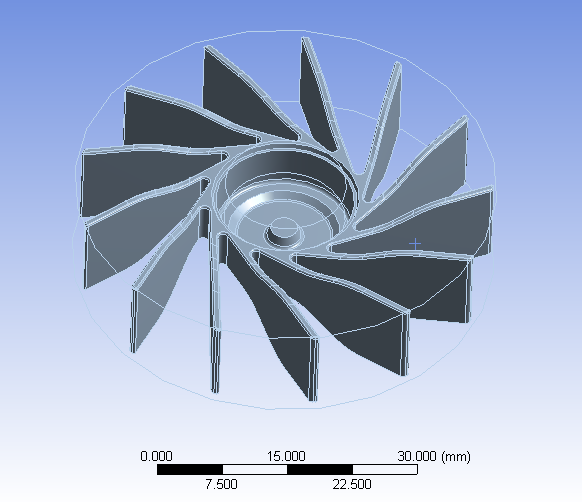
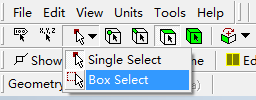
2.9 在工具栏中将Select Mode选择为Box Select,然后在视图窗口中划一个矩形区域选中所有的风扇叶片Faces,并定义新名称为fan。
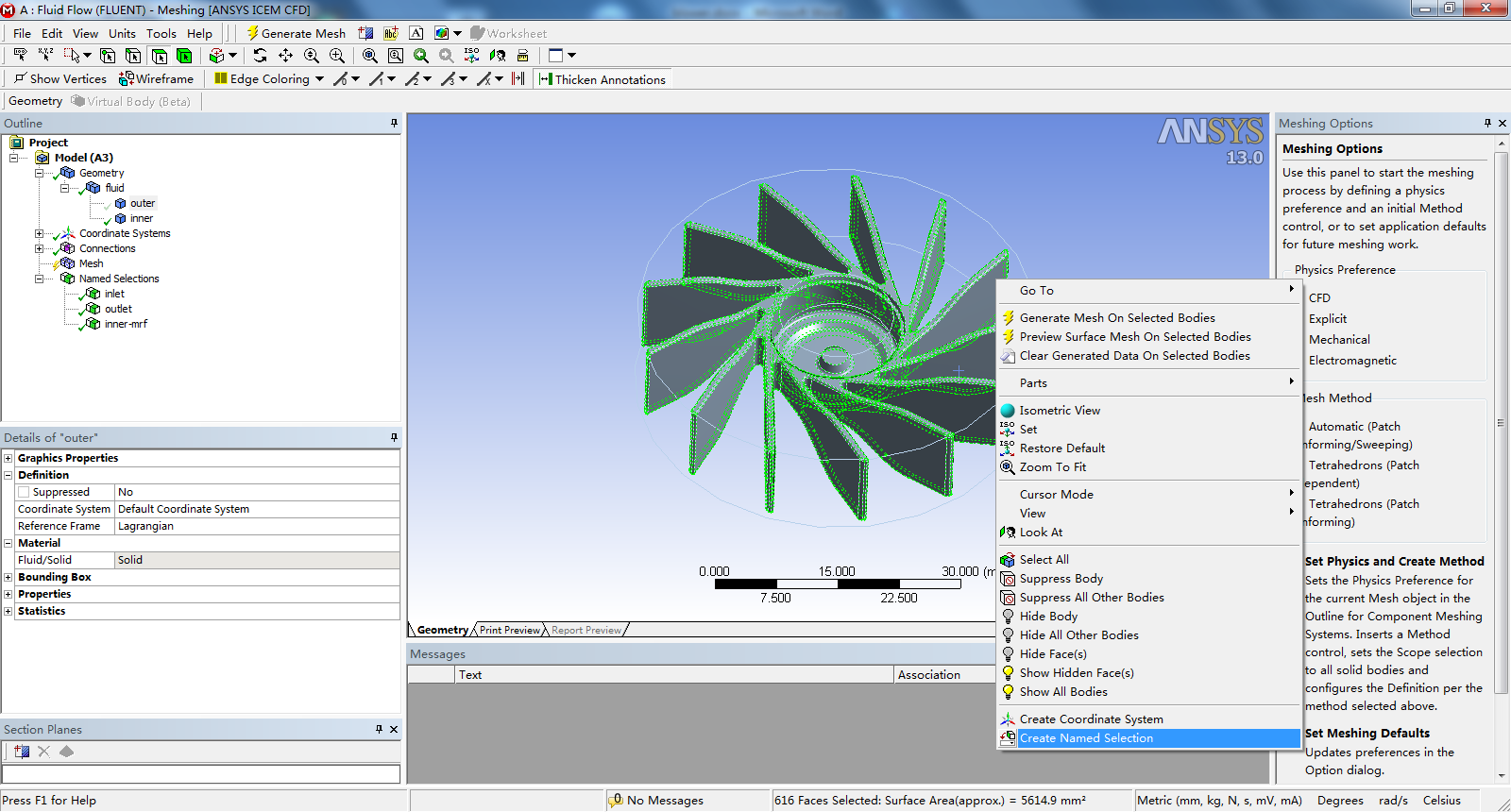
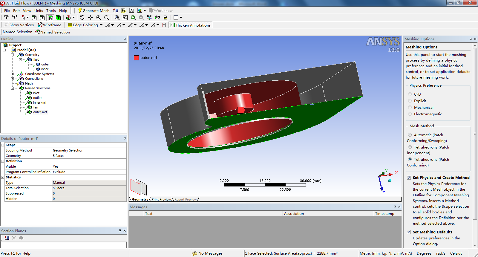
2.10 在目录树中的Geometry节点,恢复outer几何实体的显示,隐藏inner几何实体。注意用好鼠标右键点击选项菜单中的Hide Face(s)、Show Hidden Face(s)等功能,选择outer几何实体中的MRF圆台表面,并定义新名称outer-mrf。
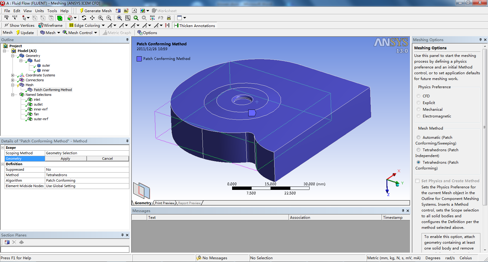
2.11 剩余的所有表面即是蜗壳表面,可以不用单独定义Name Selection,因为它们到fluent中后会保留一个统一的默认名称,到fluent中再做修改即可。
2.12 鼠标右键点击目录树中的Mesh节点,选择Insert --> Method,将Method的Algorithm设定为Patch Conforming。在Patch Conforming Method的属性窗口中,Geometry中选择两个几何实体作为划分网格的区域,点击Geometry中的Apply。(选择的时候通过视图窗口左下角的小平面可以更方便的选择一些不易选中的对象)
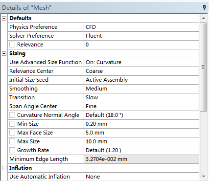
2.13 在目录树中Mesh节点的详细设定中,做如下设定:
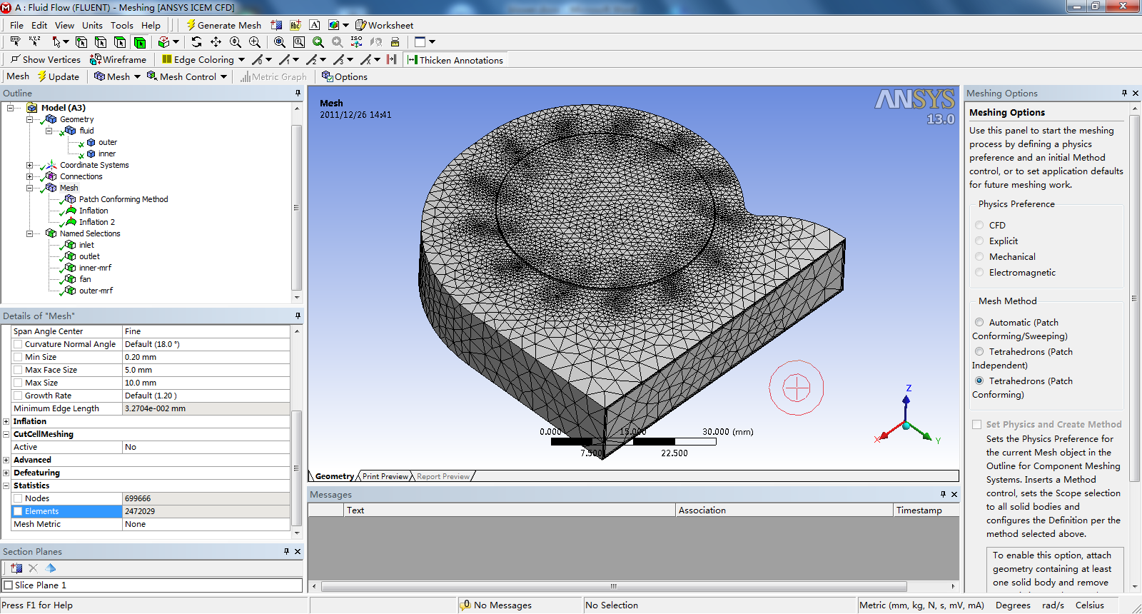
Physics Preference设定为CFD,Solver Preference设定为Fluent。Sizing中的Min Size全局最小尺寸设定为0.2 mm,Max Face Size设定为5 mm,Max Size设定为10 mm。
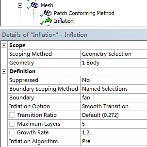
2.14 鼠标右键点击目录树中的Mesh节点,选择Insert --> Inflation,详细定义Inflation中的Geometry为inner区域,Boundary使用Named Selections方法定义fan表面做拉伸,其余选项保留默认,为扇叶表面拉伸5层边界层网格。
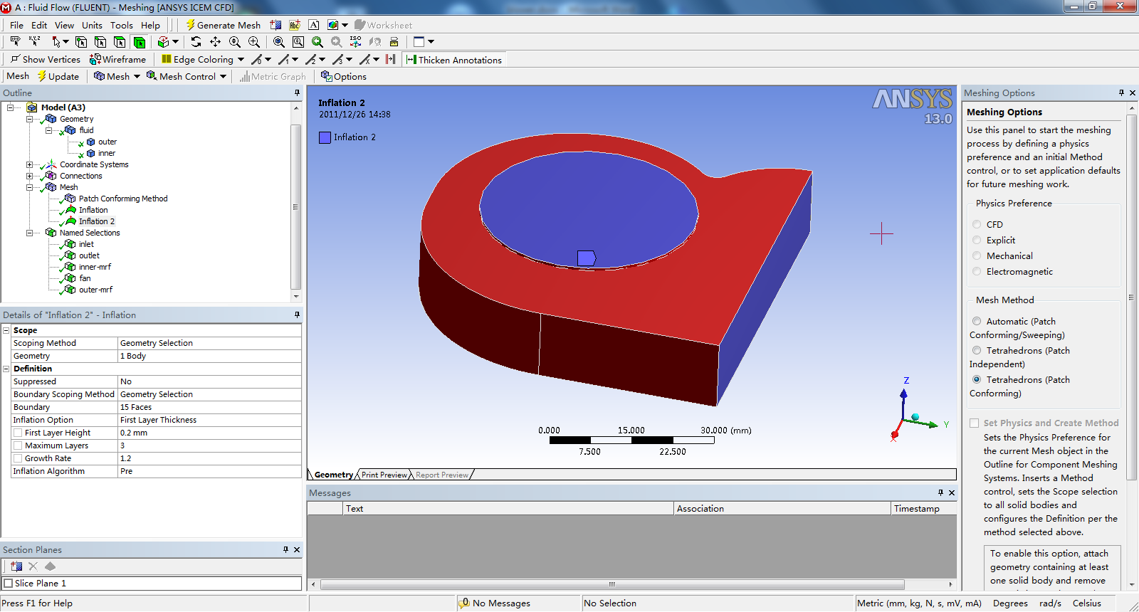
2.15 再次鼠标右键点击目录树中的Mesh节点,选择Insert --> Inflation,详细定义Inflation 2中的Geometry为outer区域,Boundary使用Geometry Selection方法选中蜗壳的各表面做拉伸,Inflation Option设定为First Layer Thickness,定义First Layer Height为0.2 mm,Maximum Layers为3,为蜗壳表面拉伸3层边界层网格。
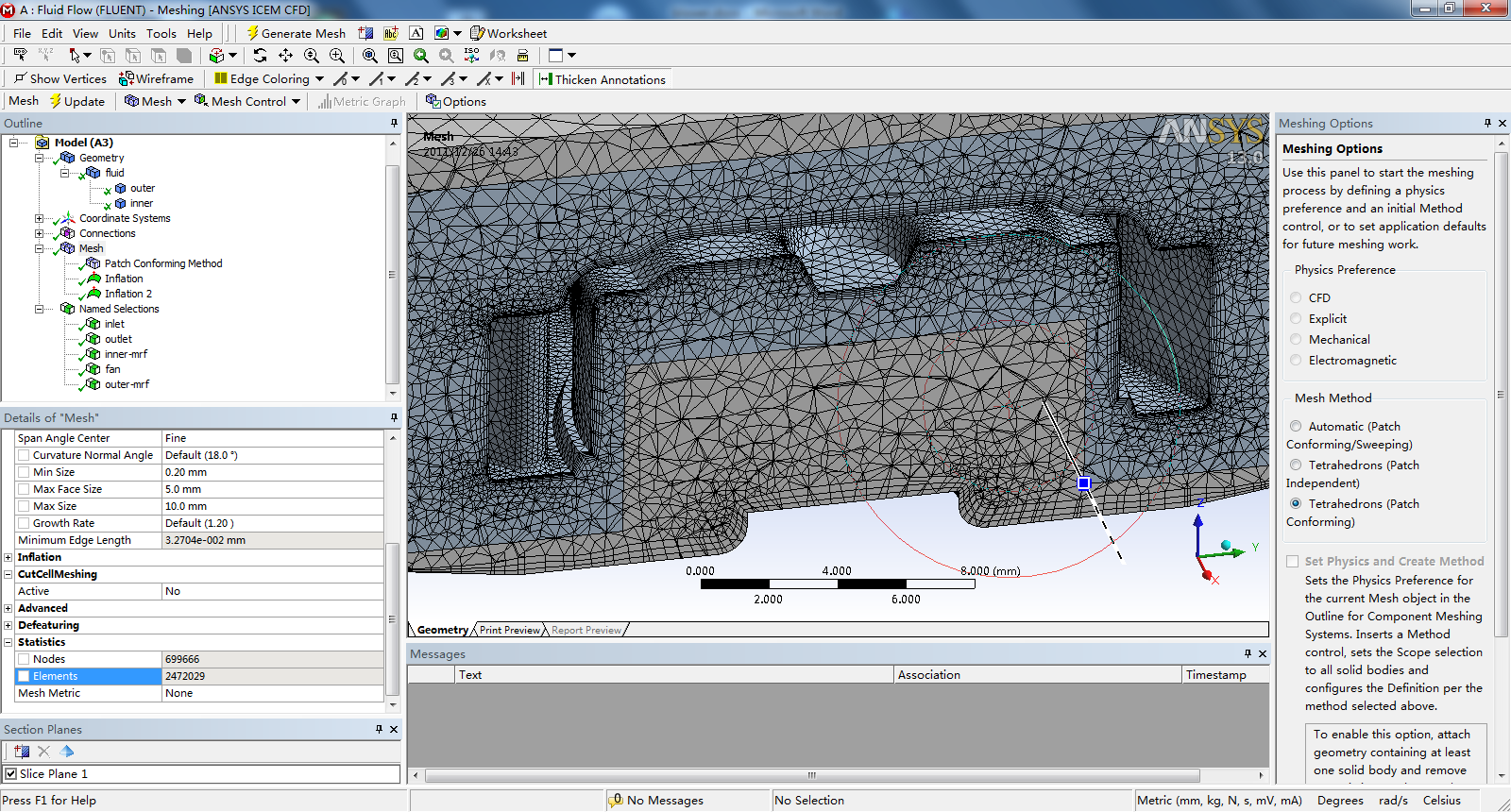
2.16 点击工具栏中的Generate Mesh按钮,等待体网格生成。最终生成了共计约247万体网格。可以点击工具栏中的New Section Plane按钮,做切面查看体网格。
2.17 File -->
Save Project,存储为fan.wbpj文件。File --> Close Meshing,关闭ANSYS Meshing。
来源:转载于:仿真秀
回复: